FreeCAD Assembly Workbench: Designing Multi-Part 3D Printed Projects
Unlock the power of FreeCAD's Assembly Workbench to design intricate, multi-part projects perfect for 3D printing. This post guides you through the process, ensuring precise fit and successful final assemblies.

Ever stared at a pile of individual 3D printed parts, beautiful on their own, but then thought, "Ugh, how am I actually going to make these fit together seamlessly?" Yeah, me too. More times than I care to admit, honestly. It’s one thing to design a cool statue or a simple phone stand, but when you start thinking about enclosures, articulated models, functional prototypes, or anything with moving parts, the game changes completely. That's when you hit the wall of multi-part projects, and if you’re not planning your assemblies from the get-go, you’re basically signing up for a future of sanding, filing, and a whole lot of colorful language.
Here at ArtOPIA Collections, running my little 3D printing business from my workshop (which, let's be real, is just a fancy name for a corner of my garage in Bengaluru), I’ve learned this the hard way. Early on, I used to design parts in isolation, cross my fingers, and hope for the best. And guess what? The best rarely happened! Gaps here, interference there, screws not lining up – it was a nightmare. Then, a few years back, I properly dove into FreeCAD’s Assembly Workbench, and honestly, it felt like someone just handed me the cheat codes to a whole new level of design freedom. It’s transformed how I approach complex prints, from custom drone frames to modular display pieces I sell on my site.
Why Assembly is Your Best Friend for Complex Prints
The thing is, when you’re printing something that needs to connect, move, or hold other components, precision is key. And that precision starts in your CAD software, not on your printer. Your Creality Ender 3 or your Anycubic Kobra, as amazing as they are for their price point (I mean, ₹20,000 for an Ender 3 Pro these days is just bonkers value!), can only reproduce what you feed them. If your design isn't accurate, your prints won't be either.
Assembly workbenches, like the one in FreeCAD, let you simulate how your individual parts will fit together *before* you even print the first layer. You can define relationships between components – like surfaces being flush, holes aligning, or parts rotating around an axis. This way, you catch all those potential fitment issues virtually, saving you precious filament (which, let’s be real, a good kilo of eSun PLA+ can set you back ₹1000-₹1200 these days, not something you want to waste on failed prints, right?) and even more precious time. Plus, it makes designing for different materials easier, accounting for slight variations in tolerance for, say, a flexible TPU part connecting to a rigid PLA one.
Why FreeCAD? And Why It's Been a Game-Changer for My Business
Now, I know what some of you might be thinking: "FreeCAD? Isn't that... complicated?" And yeah, it can be. It’s not as immediately intuitive as something like Tinkercad, and it definitely has a steeper learning curve than, say, Fusion 360 (which, let's not forget, also has its own complexities and a much higher price tag for commercial use once you're out of the hobbyist tier). But here’s the deal: FreeCAD is absolutely FREE. Like, no-strings-attached, open-source, community-driven free. For a small business like mine, where every rupee counts, that's not just a bonus; it’s a necessity.
It means I can invest more in quality filaments like Polymaker or sturdy printer upgrades, rather than shelling out thousands of rupees every year for software subscriptions. And over time, I've found FreeCAD to be incredibly powerful. It might not have the polished UI of some commercial packages, but it can do almost anything you'd need for mechanical design, and often in multiple ways, thanks to its modular workbench architecture. The community support is fantastic too, with tons of forums and tutorials online. You just have to be willing to roll up your sleeves a bit.
Diving into the FreeCAD Assembly Workbench
So, you've got your individual parts designed in, say, the Part Design Workbench. Maybe you've made a cool housing for a Raspberry Pi or a multi-segment action figure. Now, how do you put them all together in FreeCAD? This is where the Assembly Workbench comes in. There are actually a few different assembly workbenches available for FreeCAD – A2+, Assembly3, Assembly4, and LinkStage3. It can be a bit confusing at first, I won't lie. I personally started with A2+, but eventually moved to Assembly4 because it felt a bit more robust and actively developed at the time. The concepts, however, are largely similar across them.
Let’s talk about the core idea, which applies to whichever workbench you pick up:
1. Components, Instances, and Containers
Think of each individual part you've designed as a "component." When you bring it into the Assembly Workbench, you're creating an "instance" of that component. You can have multiple instances of the same component (e.g., four identical legs for a table, or multiple copies of a screw). These instances are then placed inside an "assembly container." This helps keep your project organized, especially when you have dozens of parts.
I usually start by creating a new empty assembly, then dragging and dropping my existing parts (saved as separate FreeCAD files, or even as bodies within the same file) into it. It’s like gathering all your ingredients before you start cooking, you know?
2. The Magic of Constraints
This is where the real power lies. Constraints are rules that define the spatial relationship between components. Instead of manually dragging and rotating parts into place (which is incredibly tedious and imprecise), you tell FreeCAD how they should relate to each other. Some of the most common constraints I use are:
- Coincident Constraint: Makes two points, lines, or planes touch each other. Super useful for aligning holes, or making surfaces flush.
- Plane Coincident (or Planar): Makes two flat surfaces lie on the same plane. I use this all the time to make sure parts sit neatly against each other.
- Concentric Constraint: Aligns the axes of two circular edges or cylindrical faces. Essential for putting a bolt through a hole, or assembling rotating shafts.
- Angle Constraint: Defines a specific angle between two faces. Great for hinges or parts that need to be set at a certain orientation.
- Distance Constraint: Sets a fixed distance between two points, planes, or axes. Perfect for maintaining specific gaps or offsets.
The trick is to use as few constraints as necessary to fully define the position of a component. Too many, and you'll run into "over-constrained" errors – basically, you're telling FreeCAD conflicting information, and it gets confused. It's a common beginner mistake, trust me, I've seen that solver error message pop up more times than I've had masala chai! You need to think about degrees of freedom – how many ways a part can move (up/down, left/right, forward/back, and rotation around X, Y, Z axes). Each constraint removes one or more of these degrees of freedom until the part is fully fixed in space relative to another component.
My Workflow for a Multi-Part Project
Let's say I'm designing a modular enclosure for a small IoT device, like an ESP32 board, that needs a base, a lid, and maybe some screw-in standoffs. Here’s a simplified version of my process:
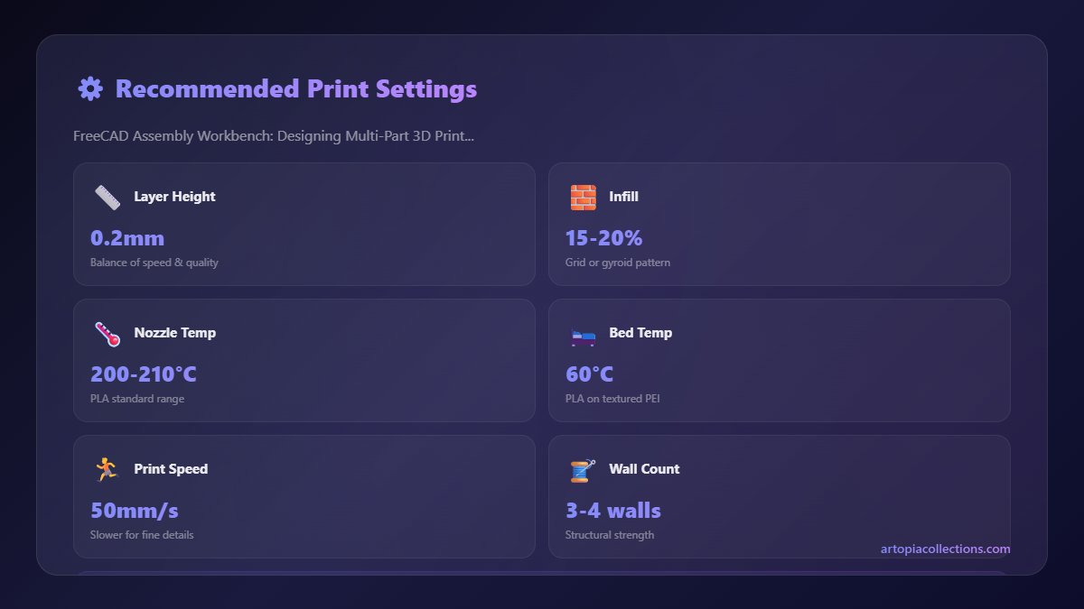
- Individual Part Design: I start in the Part Design Workbench. Each component (base, lid, standoff) is designed as a separate "Body." I make sure to include all necessary features – mounting holes, cutouts for ports, snap-fit features, etc. I also keep my tolerances in mind; for FDM printing, I usually add a 0.2-0.3mm clearance for mating parts, especially for holes and pins.
- New Assembly Document: Once my individual parts are done, I create a new FreeCAD document and switch to the Assembly4 Workbench (or whichever one you prefer).
- Importing Parts: I then "link" or "import" my individual part files into this new assembly document. This creates instances of those parts.
- Positioning the First Part: The first part I bring in (usually the main base) becomes the "anchor." I typically fix its position relative to the assembly's origin so it doesn't float around.
- Applying Constraints: Now, the fun begins. I start bringing in the other parts one by one and apply constraints.
- For the lid, I might use a "plane coincident" constraint between the top surface of the base and the bottom surface of the lid.
- Then, I'd use "concentric" constraints to align the screw holes in the lid with the corresponding holes or bosses in the base.
- If there are snap-fit features, I'd constrain them to engage correctly, maybe using "point on face" or "edge on edge" constraints.
- Testing Movement (if applicable): If I have moving parts, like a hinge, I'll define an axis of rotation and make sure all other constraints allow for that movement while preventing unwanted wiggling. FreeCAD lets you manipulate the assembly to check for interferences or binding. It's not a full-blown motion simulator like some high-end CAD software, but it's more than enough for 3D printing applications.
- Checking for Conflicts: If the solver throws an error, I go back and check my constraints. It often means two constraints are fighting each other. Sometimes, I'll temporarily disable a constraint to see what's causing the problem.
- Final Review and Export: Once everything looks good, I’ll take a final look at the assembled model. From here, you can export individual parts as STLs for slicing, or sometimes even the whole assembly if you plan to print it as a single piece (though for multi-part prints, separate STLs are usually the way to go).
One time, I was working on a custom articulating stand for a client's action figure collection. It had about 15 different printed parts – joints, clips, base, arms, all needing specific clearances and rotational limits. Without the Assembly Workbench, that project would have been pure hell. But by building it virtually first, I caught several interference issues and tolerance problems that would have resulted in days of reprinting and redesigning. Saved me a ton of headache, yaar.
Tips for Success with FreeCAD Assembly
- Start Simple: Don't try to build a complex engine on your first go. Practice with something basic like two blocks joining, or a bolt and nut.
- Organize Your Files: Keep your individual part files in a dedicated folder. This makes linking them to your assembly much easier.
- Name Your Stuff: Give meaningful names to your Bodies, sketches, and constraints. "Body001," "Sketch002" quickly becomes unmanageable. Trust me on this!
- Save Frequently: FreeCAD can crash (like any software, especially if you’re doing something complex). Ctrl+S is your friend.
- Use Datum Planes/Axes: For precise constraint application, especially with complex geometry, creating Datum Planes and Axes (reference geometry) can be a lifesaver.
- Embrace the Community: If you get stuck, the FreeCAD forums are incredibly active and helpful. YouTube also has some excellent tutorials.
And hey, if you're looking for some reliable filament to bring your assembled designs to life, I usually stock up on good quality PLA from Amazon.in. It’s always good to have a few spools handy, especially if you're experimenting with assemblies. For more robust prototypes, PETG is fantastic, like this Esun PETG, though it can be a bit trickier to print than PLA.
Final Thoughts: Just Dive In!
Look, I get it. FreeCAD, especially its Assembly Workbench, can feel intimidating at first. It’s a powerful tool, and with power often comes a bit of complexity. But for any serious 3D printing enthusiast, and especially for anyone running a small business like mine, mastering it is incredibly rewarding. It unlocks a whole new dimension of design, allowing you to create functional, multi-part projects with confidence and precision.
It’s about more than just making cool prints; it’s about making prints that *work*. So, if you've been putting off learning it, now’s the time. Download FreeCAD, grab a simple multi-part design (maybe one of those modular storage boxes or a simple articulated toy), and start experimenting. The frustration might be real initially, but the satisfaction of seeing your perfectly assembled virtual design come to life on your print bed is unbeatable. And when you create something awesome, do check out my own collection of 3D printed goodies for inspiration, or just to see what’s possible with a bit of design know-how!


