How to Design 3D Printed Gears That Actually Work in Fusion 360
Designing 3D printed gears can be tricky, often leading to non-functional parts. This guide in Fusion 360 will teach you the principles and techniques to create gears that actually work, every single time.

Cracked a Gear? Don't Buy, Design It! How to Make 3D Printed Gears That Actually Work in Fusion 360
Oh man, I know the feeling. You've got some cool gadget, maybe a kid's toy, or even a part of your washing machine, and BAM! A tiny plastic gear gives up the ghost. It's frustrating, right? You search online, but a replacement is either ridiculously expensive, takes weeks to ship from some far-off land, or just doesn't exist. You've got a 3D printer sitting there, humming away, and you think, "Can't I just print one?" And then you try. You design something quick, print it, and... it grinds, it slips, it breaks within minutes. Yeah, I've been there, more times than I'd like to admit. But here's the deal: designing 3D printed gears that actually work, that mesh perfectly and last, is totally doable. It just takes a little know-how, and honestly, Fusion 360 is your best friend for this.
From my little workshop here in India, where the hum of my Creality Ender 3 V2 and Anycubic Kobra are pretty much constant background music, I've designed and printed countless gears – for client projects, for fixing things around the house, and even for some of the quirky art pieces we make at Artopia Collections. It's incredibly satisfying when you replace that broken part with something you made yourself, and it works flawlessly. So, let's dive into how you can do it too, specifically using Fusion 360.
Why Even Bother 3D Printing Gears?
Look, I get it. Metal gears are obviously superior for heavy-duty applications. But for so many things, especially prototypes, hobby projects, or those pesky replacement parts, 3D printing is a game-changer. Imagine needing a custom gear with a weird number of teeth or a specific hub. Good luck finding that off-the-shelf! With Fusion 360 and your printer, you can iterate quickly, test designs, and have a functional part in hours, not weeks. Plus, it's a huge money saver. A small custom gear might cost you ₹500-₹1000 to get machined, but if you print it yourself, it's literally ₹5-₹10 worth of filament. That's a no-brainer, isn't it?
The Secret Sauce: Involute Profiles and the Magic of Parameters
The first, and probably most crucial, thing you need to understand about gears is that they aren't just pointy triangles sticking out of a circle. If you try to design them like that, they'll grind, they'll wear out instantly, and they'll transmit power unevenly. The real magic lies in something called an involute profile. This fancy word basically means the tooth shape is designed in such a way that as two gears mesh, they roll smoothly against each other, minimizing friction and ensuring constant velocity transmission. It's engineering brilliance, honestly.
Now, before you panic and think you need to learn advanced calculus to draw involute curves, relax! Fusion 360 has our back. It has a fantastic built-in tool that does all the complex math for us. Hallelujah for modern CAD software, right?
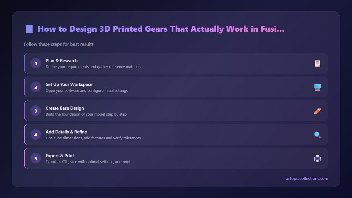
Designing Your Gear in Fusion 360: A Step-by-Step Guide
Open up Fusion 360. If you're new to it, there are tons of great tutorials online to get you started with the basics. But for gears, we're going to use a specific command.
1. Access the Spur Gear Command: Head up to the "Add-Ins" tab in your toolbar. You might find "Spur Gear" directly under "Create" in the Solid tab depending on your Fusion 360 version. If not, go to "Add-Ins" -> "Scripts and Add-Ins" and look for "Spur Gear" in the "Fusion 360 Samples" section. You can run it from there. I personally keep it pinned to my toolbar because I use it so often!
2. Understand the Parameters (This is Key!): Once you run the command, a dialog box will pop up with a bunch of numbers. Don't just hit OK! Each of these parameters is vital for making your gears mesh correctly. And trust me, getting these right here will save you so much frustration later on.
- Pressure Angle (usually 20 degrees): This is an engineering standard. For almost all applications, especially 3D printed ones, stick to 20 degrees. It's the angle at which the force is transmitted between the teeth. Don't mess with this unless you absolutely know what you're doing and have a specific reason.
- Module (the big one!): This defines the size of your gear teeth. It's the pitch diameter divided by the number of teeth. The critical thing here is that all mating gears MUST have the same module! If you have a Module 1 gear trying to mesh with a Module 2 gear, it's like trying to fit a square peg in a round hole – it just won't work. Start with a Module of 1.0 or 1.5 for most general purposes. If you need smaller, more delicate gears, go lower (e.g., 0.5); for larger, stronger gears, go higher (e.g., 2.0 or 3.0).
- Number of Teeth: This is straightforward. How many teeth do you want on your gear? Remember, the more teeth, the larger the gear's diameter for a given module. For a 1:2 ratio, you'd design one gear with, say, 20 teeth and another with 40 teeth (assuming the same module!).
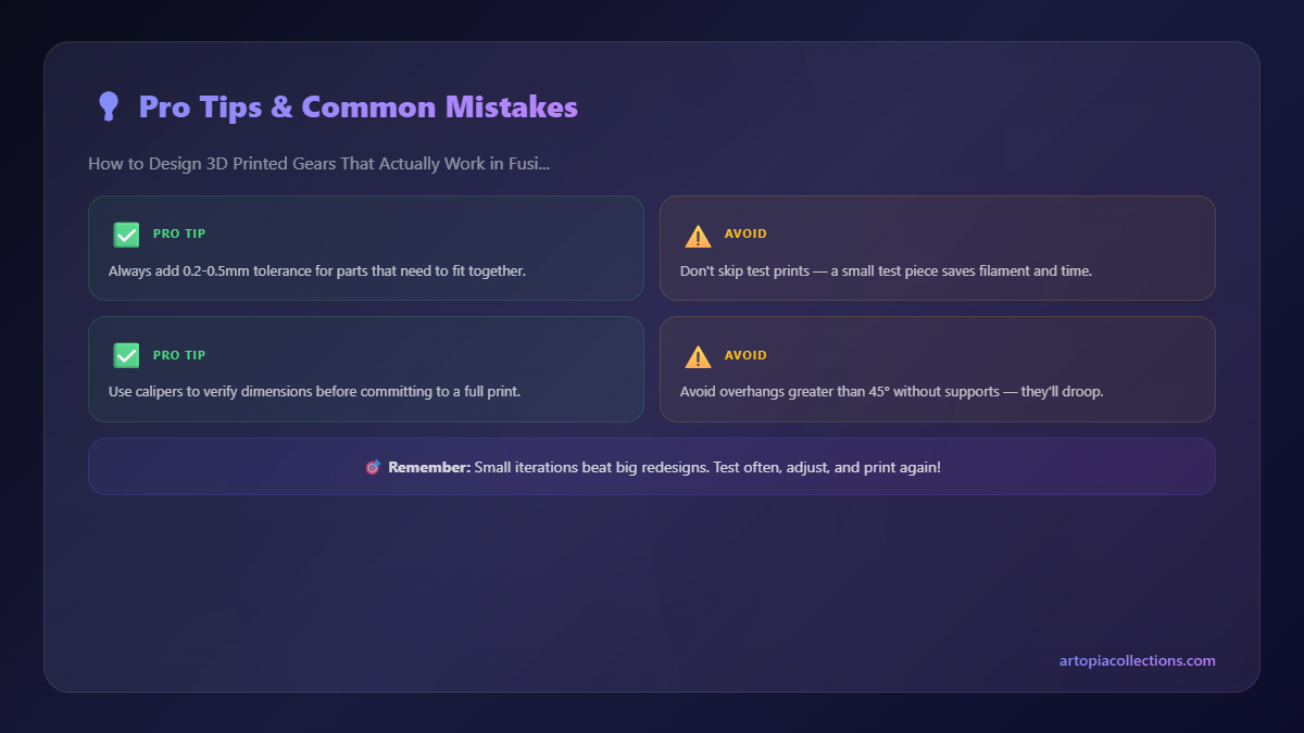
- Backlash (SUPER IMPORTANT for 3D Printing!): This is the amount of clearance or "play" between meshing teeth. In machined metal gears, you want minimal backlash for precision. But for 3D printing, you absolutely *need* some! Why? Because 3D printers aren't perfect. Filaments shrink slightly, layers aren't perfectly smooth, and you get "elephant's foot" on the first layer. If you design with zero backlash, your gears will bind and lock up.
I usually start with a backlash of 0.2mm to 0.4mm for PLA or PETG. For larger gears, or if your printer isn't super dialled in, you might even go up to 0.5mm. It's a bit of an empirical thing, meaning you might have to print a test pair and adjust. But trust me, don't skip this!
- Root Fillet Radius: This is the curve at the base of the tooth. A small fillet helps distribute stress and prevent the teeth from breaking at the root. Leave it at the default for starters, usually 0.3mm to 0.5mm is fine.
- Gear Thickness: How "thick" do you want your gear to be? This depends on your application and strength requirements. Generally, thicker gears are stronger, but use more material and might not fit your enclosure.
- Hole Diameter: This is for the shaft that goes through your gear. Remember to add a small tolerance here too! If your shaft is 5mm, don't make the hole exactly 5mm. Make it 5.1mm or 5.2mm to ensure it fits without forcing. Again, filament shrinkage and printer precision play a role here.
Once you've set all your parameters, hit OK. Fusion 360 will generate a perfect involute spur gear for you. If you need a second gear to mesh with it, just run the command again, keeping the same Module and Pressure Angle, but changing the Number of Teeth as needed.
Beyond the Design: Making Them Work in Reality
Designing in Fusion 360 is half the battle; the other half is getting a good print. Here's what I've learned after countless prints and more than a few failures:
1. Filament Choice Matters, Big Time!
- PLA: Great for prototyping, low-stress applications. It's easy to print, fairly rigid, and cheap (you can get good quality PLA for around ₹1500-₹2000 per kg from brands like eSun, Overture, or even local Indian brands). But it's brittle and softens at relatively low temperatures, so not ideal for anything that gets hot or takes a beating.
- PETG: This is my go-to for most functional gears. It's much stronger, more flexible, and more temperature-resistant than PLA. It's a bit trickier to print (stringing can be an issue), but well worth the effort for functional parts. A good PETG spool will set you back about ₹1800-₹2500 per kg.
- ABS/ASA: If you need maximum strength and heat resistance, these are your choices. But they are notoriously difficult to print without an enclosure (warping, fumes). For most home users, PETG is a better balance of performance and printability.
2. Slicer Settings are Critical
Your slicer (Cura, PrusaSlicer, Simplify3D) translates your 3D model into printer instructions. Tweaking these settings can make or break your gears.
- Layer Height: For gears, I always recommend a finer layer height, like 0.12mm or 0.16mm. This results in smoother tooth profiles and better meshing.
- Infill: Don't skimp on infill! For gears, I usually go for 50-80% infill, sometimes even 100% for very small, high-stress gears. A grid or rectilinear infill pattern works well.
- Print Speed: Slow down! For precision parts like gears, a slower print speed (e.g., 40-60mm/s) allows your printer to lay down plastic more accurately, reducing wobble and improving detail.
- Horizontal Expansion / Hole Compensation: This is where you combat "elephant's foot" and fine-tune holes. In Cura, it's called "Horizontal Expansion." If your holes are always too small, or your gear teeth are fusing slightly at the base, try a negative value here (e.g., -0.1mm or -0.2mm). Experimentation is key!
- Retraction: Make sure your retraction settings are dialled in to minimize stringing. Even tiny strings between teeth can cause binding.
3. Post-Processing and Lubrication
Once printed, a little TLC goes a long way. Use a deburring tool or a hobby knife to carefully remove any tiny imperfections, strings, or blobs from the teeth. Make sure the bore for the shaft is clean. Test the fit of the shaft. You might need a small drill bit (hand-turned, don't overdo it with a power drill!) to ream out the hole slightly.
And finally, lubrication! For plastic gears, a silicone-based grease works wonders. It reduces friction, wear, and makes everything run much smoother. You can find small tubes of silicone grease at most hardware stores or online for ₹100-₹300.
Troubleshooting Common Gear Problems
- Gears Binding / Too Tight:
- Increase backlash in Fusion 360 (try 0.3mm or 0.4mm).
- Use negative Horizontal Expansion in your slicer to compensate for elephant's foot.
- Check for print imperfections/strings between teeth.
- Gears Slipping / Too Loose:
- Decrease backlash (but not to zero!).
- Ensure both gears have the exact same Module and Pressure Angle.
- Check for under-extrusion during printing, which can make teeth thinner.
- Teeth Breaking:
- Increase infill percentage.
- Consider a stronger filament like PETG.
- Check your Root Fillet Radius in Fusion 360; increase it slightly if it's too sharp.
- Ensure gears aren't being subjected to excessive force beyond their material limits.
My Experience and a Little Plug
Honestly, learning to design and print functional gears has been one of the most rewarding skills I've picked up in 3D printing. It's allowed me to fix so many things that would otherwise be trash, and it's opened up whole new possibilities for custom designs in my business. We've even incorporated some intricate gear mechanisms into kinetic sculptures and functional prototypes for clients. The precision and customization you get are just unmatched.
So, if you're ever looking for custom 3D printed parts or even some unique gifts, do check out what we're cooking up over at Artopia Collections. We love tackling complex challenges, and trust me, if it involves gears, we know our stuff!
Go On, Give it a Try!
Don't be intimidated by the numbers and parameters. Start simple. Design a small pair of 20-tooth gears with a Module of 1.0, 20-degree pressure angle, and 0.3mm backlash. Print them out, test them, and iterate. That's the beauty of 3D printing, isn't it? You learn by doing. And once you nail that perfect mesh, the satisfaction is truly something else. Happy printing, my friends!


