How to Design Snap-Fit Joints in Fusion 360 for 3D Printing
Discover how to effectively design snap-fit joints using Fusion 360 for your 3D printing projects. This guide will help you create strong, tool-free assemblies that are easy to print and use.
Artopia Collections Blog Team9 May 202611 min read

Snap, Crackle, POP! Designing Perfect Snap-Fit Joints in Fusion 360 (My Indian 3D Printing Secrets!)
You know that feeling, right? You've just spent hours designing something super cool in Fusion 360, your printer has hummed away all night, and now you have two perfect halves. You bring them together, full of anticipation, hoping for that satisfying *click*, that snug fit that screams "I made this!" But instead... *thud*. Or worse, *crack*. Or maybe it just wobbles like a rickety autorickshaw on a potholed road. Ugh, the frustration is real, bhai! I've been there, countless times, with custom enclosures for clients or even just simple prototypes for myself. That's why mastering snap-fit joints isn't just a skill; it's practically a superpower for any 3D printing enthusiast, especially here in India where *jugaad* (innovative, frugal solutions) is practically a way of life.Why Snap-Fits Are Your New Best Friend (and Mine!)
Honestly, when I first started my little 3D printing business, Artopia Collections, I used to dread assembly. Screws? So many tiny screws, fiddly nuts, and the constant worry of stripping threads in plastic. Glues? Messy, permanent, and sometimes just ugly. Then I truly dived deep into snap-fits, and man, it was a game-changer. They make assembly a breeze, often require no extra hardware, and can look incredibly clean and professional. Plus, for things you might need to open and close often – like a battery compartment or a custom electronics enclosure – they're just fantastic. Imagine making a custom storage box for your filament spools, and the lid just *snaps* shut perfectly. Bliss! So, today, I want to walk you through my process, my little *desi* guide, to designing robust, reliable snap-fit joints in Fusion 360. We'll talk about the theory, the practical steps, and all the little tricks I've picked up from countless failed prints and late-night redesigns.Getting Started: The Humble Cantilever Beam
At its heart, most common snap-fit joints for 3D printing are variations of a cantilever beam. Think of it like a diving board. One end is fixed, and the other end (the one with the hook) is free to flex and then spring back into place. Simple, right? But the magic is in getting the dimensions just right so it flexes enough to engage, but not so much that it breaks, and then locks securely. Material Matters, Especially in Indian Weather! Before we even touch Fusion 360, let's talk about materials. This is absolutely critical, especially with our diverse Indian climate. * PLA: Great for prototyping, super easy to print, and relatively cheap (you can get a good kilo for around ₹900-₹1200 from brands like eSun, Anycubic, or local ones). But it's stiff and can be brittle. Snap fits in PLA need to be designed with more generous flex and thicker beams to prevent snapping. It also struggles with heat, so a snap fit on a car dashboard in Chennai? Forget about it. * PETG: My personal favourite for snap fits! It's got excellent layer adhesion, good impact resistance, and a bit of flexibility – perfect for those cantilever beams. It handles higher temperatures better than PLA and is still quite easy to print. A good roll of PETG might set you back ₹1200-₹1800. I often use PETG from Overture or sometimes local brands I find on Amazon.in (Check out good quality PETG filament here: PETG Filament on Amazon.in). * ABS/ASA: These offer even more flexibility and durability, especially for outdoor or high-temp applications. But, they're trickier to print (warping, fumes) and usually need an enclosure. If you're printing on an Ender 3 (like many of us in India), you might struggle without proper setup. So, I mostly stick to PETG unless a client specifically asks for ABS. For this guide, let's assume we're primarily designing for PETG, as it strikes the best balance.Designing in Fusion 360: Let's Get Our Hands Dirty!
Okay, fire up Fusion 360. I'm assuming you're familiar with the basics – sketching, extruding, etc. If not, don't worry, there are tons of great tutorials out there! We're going to design a simple snap-fit, essentially a male tab with a hook and a female receiver slot.Step 1: The Foundation – Your Main Body
First, let's create the main body where our snap fit will live. 1. Create a New Component: Always start with components. Trust me, it makes life so much easier for asse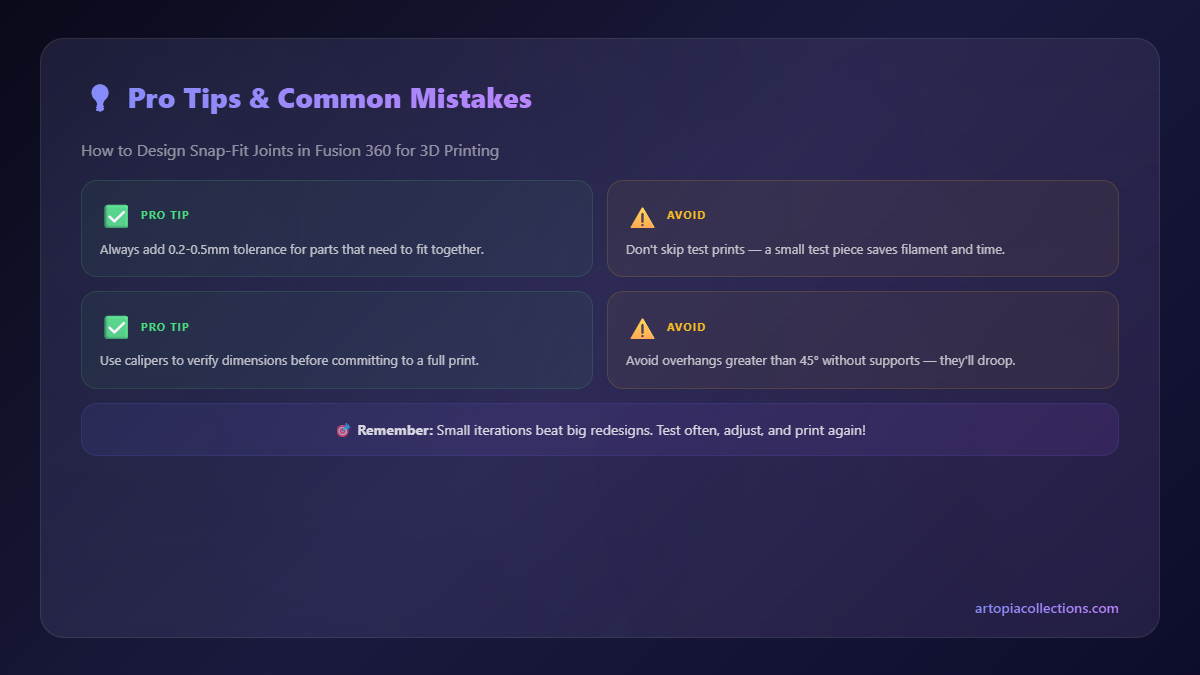
Step 2: Building the Cantilever Beam (The "Snapper")
Now for the magic part – the actual snap mechanism. 1. Activate Main Component: Go back to your main top-level component. 2. New Component for the Tab: Create another new component. Let's call it "Snap_Tab." This is good practice for modular design. 3. Sketch the Beam: Activate "Snap_Tab." Create a sketch on one of the faces of your "Main_Body" where you want the snap to attach. * Draw a rectangle. This will be your cantilever beam. Its dimensions are crucial: * Length: This determines how much it can flex. Longer beams flex more easily but can be weaker. Start with something around 15-20mm long. * Width: This will be the width of your snap feature. Let's go for 5mm. * Thickness: This is the thickness of the beam itself. For PETG, I usually start with 1.5mm to 2mm. Thicker means stiffer, thinner means more flexible but weaker. Let's use 1.8mm for now. * Position it appropriately on your main body. 4. Extrude the Beam: Extrude this sketch outwards from the main body. The extrusion distance should be enough to create a substantial hook at the end, say 8mm. Make sure "Operation" is set to "Join" with the "Main_Body" or a "New Body" if you prefer to keep it separate initially, but for a snap tab that's part of a body, "Join" is fine.Step 3: Crafting the Hook Feature
This is where it locks! 1. New Sketch on the Beam's End: Create a sketch on the very end face of the cantilever beam you just extruded. 2. Draw the Hook Profile: * Draw a triangle or a trapezoid shape. This is your "ramp" and "locking" surface. * Ramp Angle: This is the angle that allows the tab to slide over the receiver. Typically, 30-45 degrees works well. Too steep, and it's hard to push in; too shallow, and it might not create enough force to flex. * Locking Angle: The critical part! This is the angle on the *other side* of the hook, which prevents it from coming out easily. For a permanent lock, make this 90 degrees (a straight vertical wall). For something you want to release, make it slightly angled, maybe 75-85 degrees. I usually go for 80 degrees for a firm but releasable snap. * Hook Depth: How far does the hook protrude? This dictates how securely it locks. Start with 0.5mm to 1mm. Too deep, and it might be impossible to release or cause too much stress; too shallow, and it might pop out. 3. Extrude the Hook: Extrude this hook profile outwards (or inwards, depending on your design) for the width of your beam (5mm in our example). Make sure it's set to "Join."Step 4: Stress Relief – Don't Forget the Fillets!
This is probably one of the most overlooked but *vital* steps. Sharp corners are stress concentrators. That's where your snap fit will inevitably crack under repeated use or even during its first assembly. 1. Apply Fillets: Use the "Fillet" tool (Modify > Fillet). * Apply a generous fillet at the base of the cantilever beam, where it connects to the main body. A radius of 1mm to 2mm is a good starting point. This distributes the stress beautifully. * Apply fillets to the internal corners of the hook feature as well. This smooths out the contact points and reduces stress.Step 5: Designing the Receiver (The "Snappee")
Now we need a place for our snap tab to click into. 1. New Component for Receiver: Create yet another new component, call it "Receiver_Body." 2. Sketch and Extrude: Create a body that will receive the snap. For instance, another 50mm x 30mm x 10mm rectangle. Position it relative to your "Main_Body" so they face each other. 3. Create the Slot/Hole: * Activate "Receiver_Body." Create a sketch on the face where the snap tab will engage. * Draw a rectangle that matches the dimensions of your snap tab's *hook* profile. * Crucial step: Tolerances and Clearances!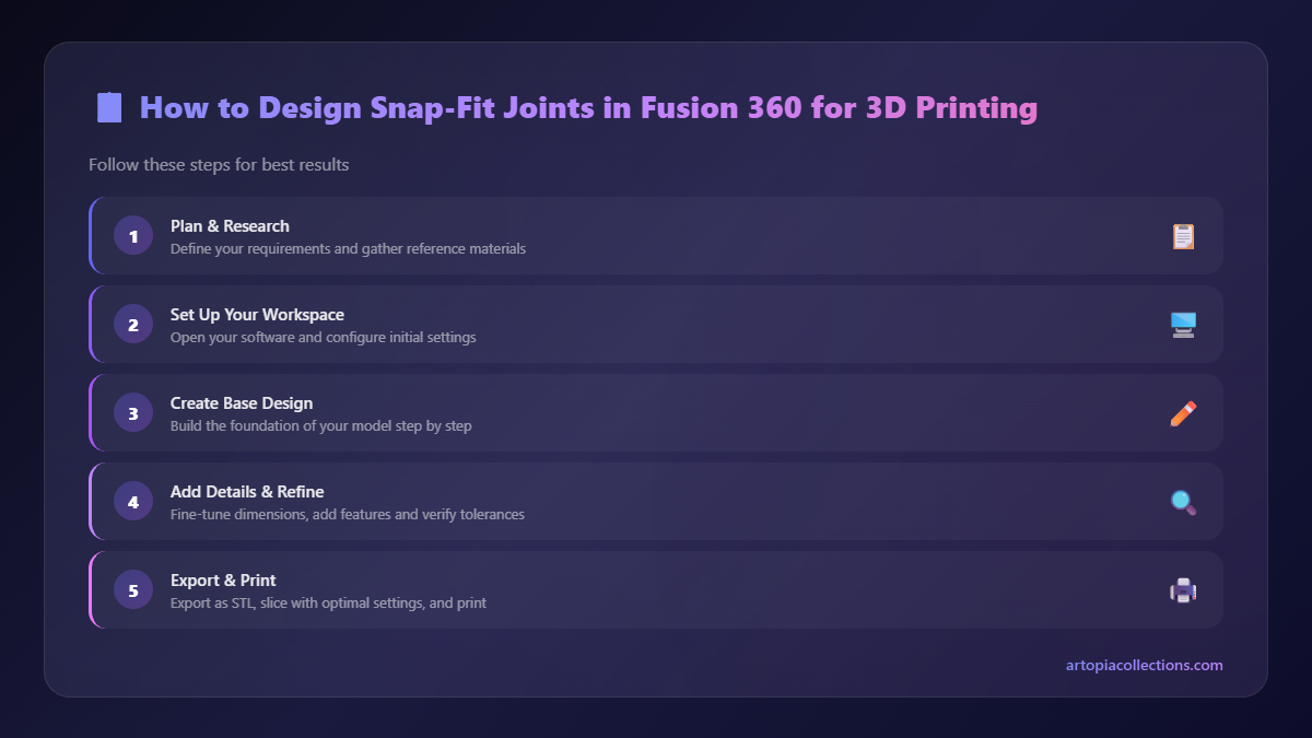 > This is where the *jugaad* truly comes in. Your 3D printer isn't perfectly precise. You need gaps.
* Clearance Around the Beam: Make the slot slightly wider than your snap tab's width (5mm). I usually add 0.2mm to 0.4mm total clearance (so, 0.1mm to 0.2mm on each side). So for a 5mm wide beam, make the slot 5.2mm to 5.4mm wide.
* Clearance Around the Hook: The depth and width of the slot where the hook engages need careful consideration. The hook itself will compress slightly. I usually design the slot to be *exactly* the size of the hook's locking profile, maybe with a tiny 0.05mm clearance if I'm feeling generous. The printer's inherent tolerance might give you enough.
* Extrude Cut: Extrude this slot sketch as a "Cut" into your "Receiver_Body." Make the cut deep enough to fully accommodate the hook's protrusion.
> This is where the *jugaad* truly comes in. Your 3D printer isn't perfectly precise. You need gaps.
* Clearance Around the Beam: Make the slot slightly wider than your snap tab's width (5mm). I usually add 0.2mm to 0.4mm total clearance (so, 0.1mm to 0.2mm on each side). So for a 5mm wide beam, make the slot 5.2mm to 5.4mm wide.
* Clearance Around the Hook: The depth and width of the slot where the hook engages need careful consideration. The hook itself will compress slightly. I usually design the slot to be *exactly* the size of the hook's locking profile, maybe with a tiny 0.05mm clearance if I'm feeling generous. The printer's inherent tolerance might give you enough.
* Extrude Cut: Extrude this slot sketch as a "Cut" into your "Receiver_Body." Make the cut deep enough to fully accommodate the hook's protrusion.


