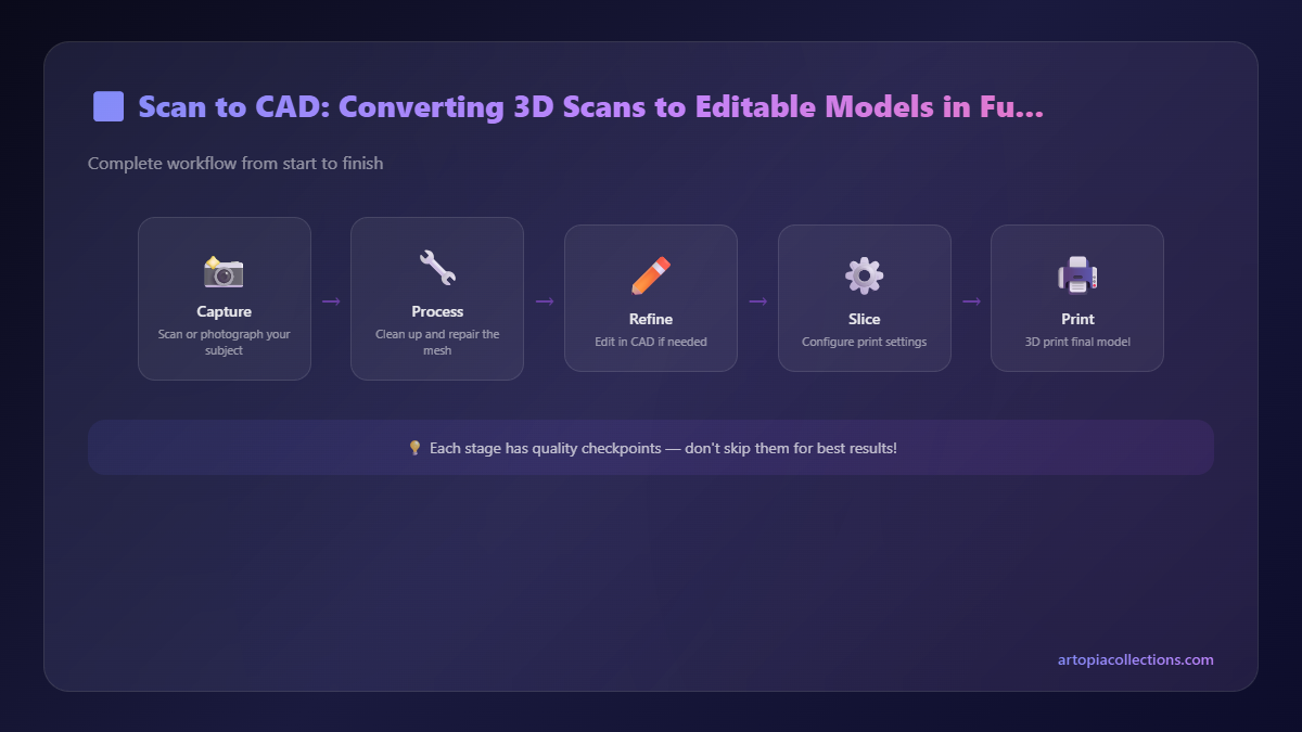
Scan to CAD: Converting 3D Scans to Editable Models in Fusion 360
This post dives into the world of converting 3D scan data into editable CAD models. Discover the essential steps and tools within Fusion 360 to bring your scanned objects to life as parametric designs.
Artopia Collections Blog Team23 May 202612 min read

When a Photo Just Won't Do: Diving Deep into Scan to CAD in Fusion 360
You know that feeling, right? That moment a customer walks in (or sends you a desperate WhatsApp message) with a broken part, a cherished antique, or just a really oddly shaped something, and they look at you with hope in their eyes, saying, "Can you 3D print this?" And it's not a simple geometric shape you can whip up in TinkerCAD in five minutes. Oh no, it's got curves, organic lines, wear and tear, and a whole story etched into its surface. For years, this was where I'd sometimes have to gently say, "I can *try* to model it by eye, but it won't be perfect, and it'll take ages." But here's the deal, folks: those days are largely behind us, thanks to a superpower called Scan to CAD, and my secret weapon, Fusion 360.The Magic and the Madness: Why Scan to CAD?
Honestly, it's a total game-changer for a small business like mine, ArtoPia Collections. Imagine someone comes to me with a broken gear from an old washing machine – a part that's impossible to find now, not even online. Or maybe it's a beautiful, intricate statue they want replicated, scaled down for a keychain, or scaled up for a garden ornament. Before, I'd be sitting there with my calipers, trying to measure every radius, every angle, every awkward curve, sketching it out on paper, and then spending hours, sometimes days, painstakingly recreating it in CAD. It was slow, prone to error, and frankly, expensive for the customer because of the labor involved. But now, with 3D scanning, we can capture the physical world, every bump and dimple, and bring it straight into the digital realm. Sounds like magic, doesn't it? Well, it is, in a way. The "madness" part comes when you realize what a 3D scanner actually gives you: a mesh. Think of it like a skin made of thousands, even millions, of tiny triangles. Beautiful for rendering, great for direct mesh printing, but absolutely useless if you want to modify it, scale it precisely, or integrate it with other parametrically designed parts. You can't just slap a hole through a mesh in the same way you can a solid body. And that, my friends, is where Scan to CAD comes in – the process of taking that messy, triangulated skin and transforming it into a clean, editable, solid 3D model.My Scan-to-CAD Workflow: From Physical to Parametric
So, how do I actually do it? Let's break down my process, starting from the physical object right up to a print-ready file.Step 1: The Scan – Capturing Reality
First off, you need a good scan. And honestly, this is where the quality of your final CAD model really begins. I've played around with a few options over the years. For simple, larger objects, photogrammetry with my phone camera and a good photogrammetry software (like Metashape or even free ones like Meshroom) can work wonders, especially if I'm careful with lighting and overlap. But for precision, or for smaller, more intricate parts, a dedicated handheld scanner is king. I've used scanners like the Revopoint POP 2 and the Creality CR-Scan Lizard. The Revopoint POP 2, for example, is fantastic for its price point (around ₹70,000 to ₹80,000 when I got mine) and gives really decent detail for a hobbyist-grade scanner. The CR-Scan Lizard is another excellent option, often a bit more affordable (around ₹50,000 to ₹60,000), and it's surprisingly user-friendly. These scanners capture incredible detail, turning a physical object into a digital mesh in minutes. Without a good scan, everything else is just guesswork, or a monumental waste of time. I personally think investing in a decent scanner is crucial if you're serious about offering this kind of service.Step 2: Initial Mesh Cleanup – Tidying Up the Triangles
Once I have my raw scan, it's almost never perfect. Scanners can miss areas, create floating bits of geometry, or capture noisy data. Before I even think about bringing it into Fusion 360, I usually run it through a dedicated mesh editing software. MeshMixer (which is free, thankfully!) is a godsend for this. I'll use it to: * Fill holes: Scanners often struggle with deep cavities or thin edges. * Remove noise/floating geometry: Sometimes you get little speckles of triangles that aren't part of the main object. * Smooth rough areas: While Scan to CAD aims for a clean solid, a little smoothing can help later. * Orient and scale: Making sure the model is roughly upright and to the correct scale. This step is critical. Trying to convert a messy mesh into CAD is like trying to build a house on a sinking foundation. You just don't do it.Step 3: Entering the Fusion 360 Arena – From Mesh to Mod
 el
el
Alright, now for the main event! Fusion 360 is an absolute powerhouse, and its Mesh workspace, combined with its traditional solid and surface modeling tools, makes it perfect for Scan to CAD.
Bringing the Mesh In:
First things first, I open Fusion 360 and go to the "Mesh" tab in the toolbar. Then, I simply hit "Insert Mesh" and bring in my cleaned-up STL or OBJ file. It appears in the workspace, looking like a ghost of the original object, all grey and triangulated.The "Do or Die" Decisions: What Approach to Take?
This is where the art and skill come in. There isn't one single "right" way to convert a mesh to CAD. It depends entirely on the geometry of the object. 1. For Organic, Freeform Shapes (Think Sculptures, Ergonomic Grips): The "Form" Workspace (T-Splines) If I'm working with something really organic, like a human bust, a complex sculpture, or an ergonomic handle, the "Form" workspace (T-Splines) in Fusion 360 is my best friend. * I'll often start by creating a primitive T-Spline body (like a box or a sphere) and then use the "Edit Form" tools to push, pull, and sculpt it to match the underlying mesh. * The "Pull" command is incredibly powerful here. It literally lets you "pull" the T-Spline vertices directly onto the mesh surface. * It's an iterative process, gently coaxing the T-Spline cage to conform to the mesh. The beauty of T-Splines is that they create perfectly smooth, continuous surfaces, which is fantastic for aesthetics and fluid designs. But it does take practice, and it's not always super precise for engineering parts. Once I'm happy, I convert the T-Spline body to a solid body. 2. For More Geometric, Contoured Shapes (Think Car Panels, Complex Housings): The "Surface" Workspace Sometimes, an object might have a mix of organic curves and defined edges, or it might need very precise surfacing. This is where the "Surface" workspace shines. * I'd use the mesh as a guide to create sketch profiles on different planes. For example, I might create multiple sketch planes along the length of an object, then use "Create Mesh Section" in the Mesh tab to project cross-sections of the mesh onto those sketch planes. * Then, using spline tools, I'll trace these projected cross-sections. And I mean *trace*. This isn't automatic; it's manual, careful work. * Once I have a series of profiles, I use surface tools like "Loft," "Sweep," or "Patch" to generate surfaces that follow these profiles. * The goal here is to build up the object using a series of precisely controlled surface patches. Eventually, these surfaces can be "Stitched" together and then "Thickened" to create a solid body. This method is incredibly powerful for complex Class A surfaces, but it's also quite demanding and requires a good understanding of surface modeling. 3. For Mechanical Parts, Broken Components, and Most Reverse Engineering: The "Solid" Workspace (Parametric Modeling) This is probably the most common scenario for me, especially when a customer brings in a broken plastic part for replication. This is where Fusion 360's traditional parametric modeling in the "Solid" workspace comes into its own. * Orienting the Mesh: First, I often use the "Align" tool in the Mesh tab to precisely orient the mesh. I might pick three points on the mesh and align them to origin planes or coordinate axes. This makes subsequent sketching much easier. * Creating Sketch Planes: I'll create construction planes strategically positioned through the mesh. These might be parallel to the XY, YZ, or XZ planes, or offset from faces, or even tangent to curves on the mesh. * Projecting Mesh Data: Here's the magic trick for parametric modeling! I go to "Create" in the Solid tab, then "Create Sketch." I select my construction plane. Now, under "Create" -> "Project/Include", there's an option called "Intersect." I select "Intersect Body" and then select my mesh. Fusion 360 will then project the intersection of the mesh with my sketch plane as sketch lines! It's not always perfect, but it gives me a fantastic starting point. * Alternatively, and often more robustly, I use the "Create Mesh Section" tool from the "Mesh" tab again. This creates an actual sketch that I can then refine. * Sketching Over the Mesh: With these projected lines as a guide, I use Fusion 360's sketching tools – lines, arcs, circles, splines – to meticulously trace over the mesh sections. I use dimensions and constraints to make these sketches precise. This is the manual, brain-power-intensive part. I'm essentially designing a *new