How to Design Press-Fit Parts in Any CAD Software for 3D Printing
Discover how to precisely design press-fit parts for 3D printing using any CAD software. This guide provides essential tips on tolerances and best practices to ensure strong, perfect-fitting assemblies.
Ever spent hours meticulously designing a multi-part 3D print, watched it slowly come to life on your printer, only to try and assemble the pieces and find they just... *flop* together? Or worse, they don't fit at all, leaving you with a frustrating gap or a broken part? Yeah, I've been there. My workshop has seen more failed fits than a Bollywood wedding planner sees last-minute guest list changes! It’s enough to make you want to throw your printer out the window. But trust me, once you master the art of the press-fit, it’s a game-changer. And it’s not as scary as it sounds, especially when you’re doing it for 3D printing.
I’m just like you, a passionate maker from India, running my small 3D printing business, Artopia Collections, out of what used to be my garage. We make everything from custom prototypes to funky home decor, and almost everything involves multiple parts fitting together beautifully. That’s where press-fits shine. No glue, no screws, just pure, satisfying mechanical magic. So, let’s ditch the frustration and dive into how you can design perfect press-fit parts in any CAD software for your 3D prints!
What Even IS a Press-Fit, Yaar? And Why Should I Care?
Basically, a press-fit (also known as an interference fit or friction fit) is when you design two parts so that one is ever-so-slightly larger than the hole it's meant to go into. When you push them together, the material deforms slightly, creating friction that holds them securely without any additional fasteners or adhesives. Think of it like a really snug lid on a container, or how some LEGO bricks click together – but way more precise.
Why bother with this? Well, for 3D printing, it's brilliant:
- Cleaner Aesthetics: No ugly screw heads or messy glue lines.
- Simpler Assembly: Just push and click! Great for kits or modular designs.
- Cost-Effective: You save on buying screws, nuts, or glues. Every rupee saved is a rupee earned, right?
- Disassembly: Often, you can take them apart and put them back together without damage, which is super handy for prototypes or repairs.
- Structural Integrity: When done right, they can be surprisingly strong.
I personally use press-fits all the time for enclosures, snap-together toys, and even intricate jewellery boxes. It just makes the final product feel so much more professional. And honestly, it’s pretty satisfying when you hear that perfect click!
The Secret Sauce: Understanding Your Printer and Tolerances
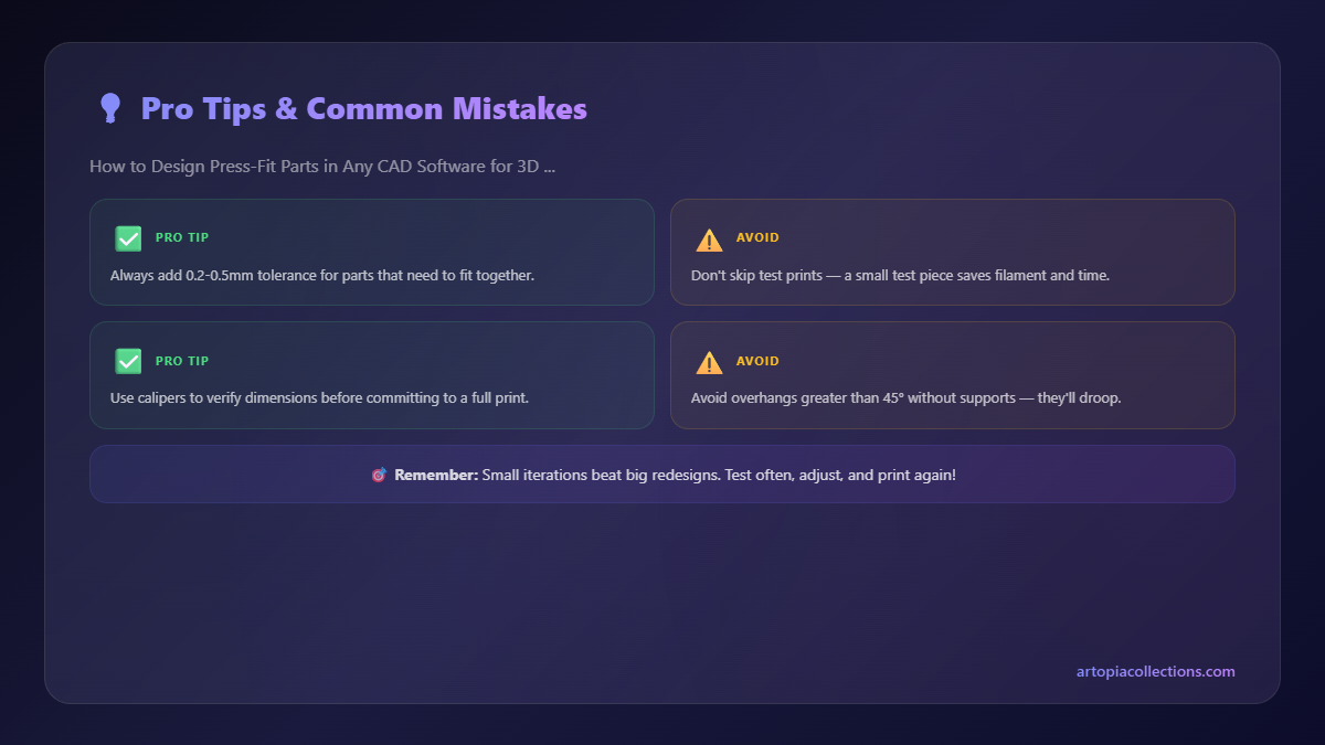
Here’s the deal: 3D printing isn't an exact science. Every printer, every roll of filament, even the ambient temperature in your room can affect the final dimensions of your print. This is why a "one-size-fits-all" tolerance for press-fits simply doesn't exist. The biggest mistake beginners make is designing parts to exact dimensions in CAD (e.g., a 10mm peg for a 10mm hole) and expecting them to fit. News flash: they won’t! Your printer will always print a hole slightly smaller, and a peg slightly larger, due to things like elephant's foot, nozzle diameter, and thermal expansion/contraction of the plastic. This is called *tolerance*.
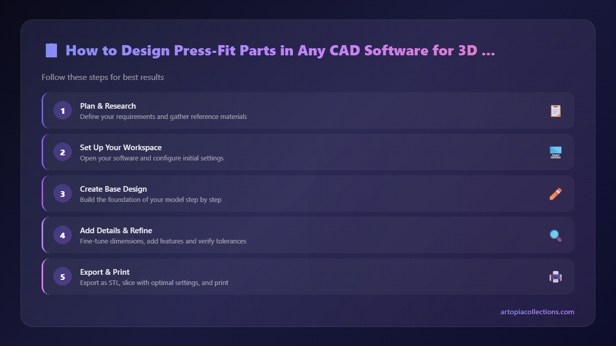
Step 1: Know Your Printer (And Your Filament) Like Your Favourite Biryani Recipe
Before you even open your CAD software, you need to understand how *your specific printer* handles dimensions. This is the most critical step, and it’s often overlooked. It's not about being fancy with a Prusa (though they are amazing, but pricey – starting at around ₹80,000 for a Mini+!). Even my trusty old Ender 3, which I bought for around ₹16,000 a few years ago (you can probably find similar entry-level printers for ₹18,000-₹25,000 now), has its quirks. Here’s what you need to do:
- Calibrate Your Extrusion: Make sure your printer is extruding accurately. An E-steps calibration is fundamental. There are tons of guides online for this.
- Print a Tolerance Test: This is non-negotiable. Search for "3D printer tolerance test" on Thingiverse or Printables. You'll find many models that have various sized pegs and holes (e.g., a series of holes with 0mm, -0.1mm, -0.2mm, +0.1mm, +0.2mm clearances).
- Test & Measure: Print this test part using the *exact filament* and *slicer settings* you plan to use for your actual project. Then, try to fit the pegs into the holes. Note which clearance works best for a snug fit.
- Get a Caliper: Seriously, if you don't have a good digital caliper, stop reading and go buy one. You can find decent ones for around ₹500-₹800, maybe even a bit less on sale. A cheap one will do fine to start. I use a simple one like this generic digital caliper; it’s accurate enough for 99% of my work. Measure the actual printed dimensions against your design. This will tell you your printer's inherent deviation.
In my experience, for a good, tight press-fit with PLA on my Ender 3, I usually aim for an interference (the peg being larger than the hole) of about 0.1mm to 0.2mm. For a loose, slip-fit, I might go for a 0.1mm to 0.2mm *clearance* (the hole being larger than the peg). But this is MY printer. YOURS might be different. That's why the tolerance test is crucial!
Designing in CAD: The Nitty-Gritty
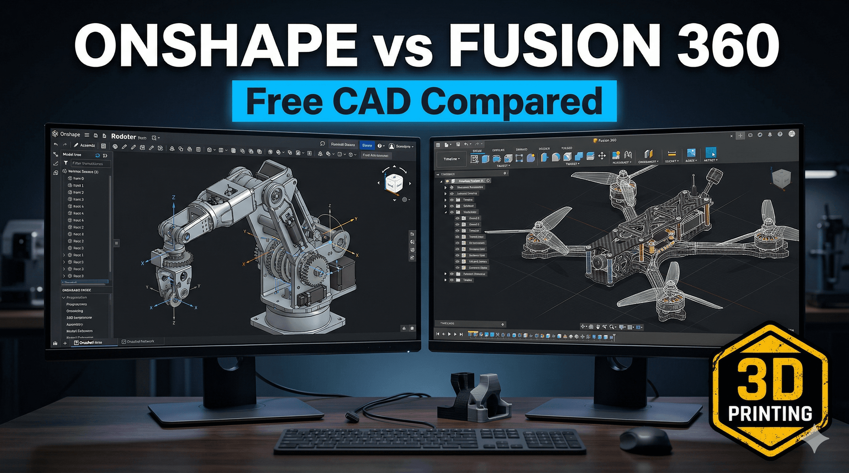
Okay, you've done your homework. You know your printer's sweet spot. Now, let’s talk CAD. Whether you're using Fusion 360, TinkerCAD, SolidWorks, Onshape, or anything else, the principles are the same.
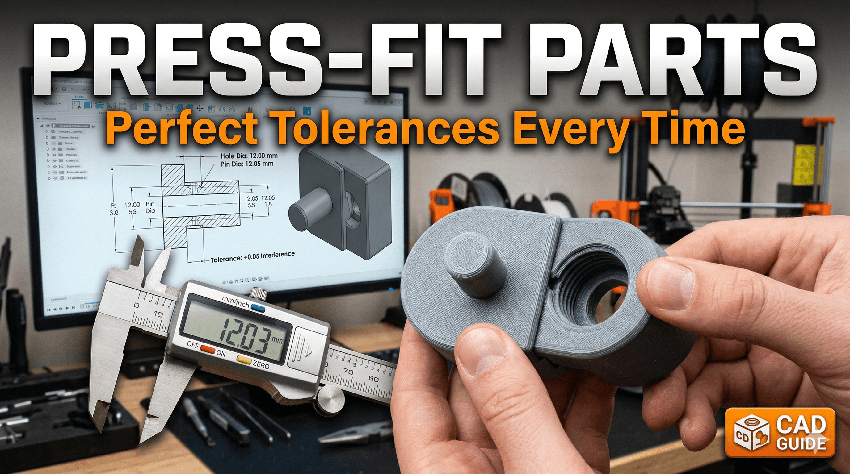
1. Peg & Hole Design: The Basics
You’ll always have two mating parts: a male part (the peg, post, or boss) and a female part (the hole, slot, or receiver).
- For the Peg: Design it to be slightly *larger* than your nominal dimension. If you want a 10mm peg, and your test showed 0.1mm interference works best, design it as 10.1mm.
- For the Hole: Design it to be slightly *smaller* than your nominal dimension. If you want a 10mm hole, and your test showed 0.1mm interference works best, design it as 9.9mm.
See what I did there? The peg is 10.1mm, the hole is 9.9mm. When they meet, you have a 0.2mm interference (10.1 - 9.9 = 0.2). I personally find this method easier to manage, adjusting both sides slightly, rather than only changing one.
Sometimes, I just make the hole the nominal size (e.g., 10mm) and then make the peg 0.15mm larger (10.15mm). It really depends on my confidence in the printer's ability to hold the hole size accurately, which varies. This is where those mild imperfections come in handy – sometimes my early designs, I swear, felt like I was just throwing darts at a board with numbers on it. But practice makes perfect, or at least, less imperfect!
2. The Importance of Chamfers and Fillets
This is where design goes from "it fits" to "it fits beautifully".
- Chamfers on the Peg: Add a small chamfer (a slight angle) to the leading edge of your peg. A 45-degree chamfer of about 0.5mm to 1mm makes a huge difference. It guides the peg into the hole smoothly, preventing binding and reducing the force needed to start the fit. Without it, you're just trying to push two blunt objects together, which can cause snapping or splitting, especially with brittle filaments like some PLAs.
- Fillets in the Hole (Optional, but Good): Adding a small fillet (a rounded edge) to the entry of the hole can also help guide the peg, though a chamfer on the peg is usually more critical. More importantly, fillets at the *base* of the peg (where it meets the main body) or around the hole can help distribute stress and prevent cracking if you’re pushing really hard.
3. Beyond Basic Circles: Other Types of Press-Fits
It's not just about circular pegs and holes!
- Rectangular/Square Pegs: These are trickier because corners are harder to manage for tolerance. Always chamfer the corners of the peg! And consider adding small fillets to the internal corners of the hole to aid assembly and reduce stress points.
- Split Pegs/Compliant Mechanisms: For a more forgiving fit, especially if you need to frequently assemble/disassemble, consider a split peg design. Imagine a cylindrical peg with a slot cut down its side, or even a cross-shape. These "fingers" can compress slightly as they enter the hole, providing a secure but less rigid fit. This is fantastic for things like battery covers or lids that need to be removed often.
- Tapered Fits: Design the peg to be slightly tapered, gradually increasing in diameter. This allows for fine-tuning the fit depth and makes insertion easier initially, tightening as you push further. Great for knobs or handles.
4. Iteration is Your Friend: Test, Test, Test!
Even after your initial tolerance test, you should always print small, representative sections of your actual parts *before* printing the whole thing. For example, if you're making an enclosure with four corner pegs, just print one corner with its mating hole. This saves a lot of time and filament. My workshop is full of these small test pieces – sometimes I feel like I'm running a tiny plastic scrap yard, but it saves me so much headache later!
And remember that thing I mentioned about specific prices earlier? Filament isn't cheap! A good kilo of PLA from brands like Ourex, eSUN, or even local Indian brands like 3DPrintz.in will cost you anywhere from ₹900 to ₹1,500. So every failed print due to bad tolerances is literally money wasted. Small test prints are a smart investment.
Speaking of filament, if you're looking for good quality PLA filament that's reliably available in India, check out some options here on Amazon.in. It really does make a difference!
Filament Choice Matters
The type of filament you use plays a significant role in how well your press-fits perform.
- PLA: The most common. It's rigid but can be brittle. A tighter interference fit (e.g., 0.15mm-0.2mm) often works well, but be careful not to overdo it or the part might crack, especially with thin walls. Chamfers are extra important here.
- PETG: My personal favourite for functional prints. It's more flexible and durable than PLA, so it can handle a bit more interference and stress. A 0.2mm-0.3mm interference often works brilliantly for a very strong fit. PETG's slight flexibility helps it 'give' a little, creating a more robust connection.
- ABS: Similar to PETG in terms of flexibility, but harder to print due to warping and fumes. If you master ABS, it offers great strength for press-fits.
- Flexible Filaments (TPU/TPE): These are fantastic for press-fits that need to be easily inserted and removed, or to act as seals. The flexibility allows for a much larger interference, as the material compresses significantly. Great for things like dust caps or vibration dampeners.
Common Troubleshooting & My Two Cents
So, you printed your parts and they're not quite right? Don’t worry, it happens to the best of us (and me, probably more often than I’d like to admit!).
- Too Loose: If your peg just slides in or wobbles, you need more interference. Increase the peg size or decrease the hole size in your CAD by another 0.05mm to 0.1mm.
- Too Tight/Won't Fit: If you're struggling to push them together, or they crack, you have too much interference. Decrease the peg size or increase the hole size in your CAD by 0.05mm to 0.1mm.
- Elephant's Foot: This is a common issue where the first layer of your print squishes out, making the base of your part slightly wider. This can make holes smaller and pegs larger at their base, causing difficulty. Adjust your initial layer height, initial layer line width, or use Z-offset calibration to mitigate it. Your slicer likely has an "elephant's foot compensation" setting too!
- Warping: If parts are warping, especially at the edges, your dimensions will be off. Ensure good bed adhesion and temperature control.
- Print Orientation: Sometimes, printing a part on its side versus flat can affect its dimensional accuracy due to anisotropy (differences in strength/accuracy depending on print direction). Keep this in mind for critical fits.
I remember this one time, I was trying to make a custom enclosure for a small sensor, and I designed the lid with what I thought was a perfect press-fit. Printed it, and... nope. Way too tight. Ended up having to sand it down by hand for ages to get it to fit, and it still looked a bit ugly. (Pro tip: don't do that. Redesign and reprint! It's faster in the long run and gives a much better result.)
When NOT to Use Press-Fits
While I'm a big fan, press-fits aren't a silver bullet for every connection. Avoid them if:
- Frequent Disassembly: If you need to take parts apart dozens of times a day, a press-fit might wear out quickly. Consider screws, magnets, or proper snap-fit latches instead.
- High Stress/Vibration: For parts under constant heavy load or vibration, press-fits might eventually loosen. Reinforce with adhesive or mechanical fasteners.
- Extreme Temperatures: If your part will experience wide temperature swings, different materials will expand and contract at different rates, potentially loosening or seizing the fit.
- Very Thin Walls: Pressing parts together can exert significant force. If your walls are too thin, they might crack or deform permanently.
Chalo, Let's Get Designing!
Mastering press-fits is one of those skills that really elevates your 3D printing game from hobbyist to serious maker. It’s all about understanding your tools, iterative design, and a little bit of patience. Don't get discouraged if your first few attempts aren't perfect. That’s totally normal! Every failed fit is a learning opportunity. Just adjust your tolerances, tweak your design, and try again. You’ll get that satisfying "click" eventually!
So, fire up your CAD software, design a simple peg and hole, run your tolerance tests, and start experimenting. Soon, you'll be designing complex, multi-part assemblies that click together like magic, making your projects look incredibly professional. And trust me, that feeling of watching perfectly designed parts slot into place? Pure joy, yaar!