How to Use Tinkercad Circuits with 3D Printed Enclosures
Discover how to elevate your electronics projects by combining Tinkercad Circuits with custom 3D printed enclosures. This post guides you through the design process, from virtual circuit breadboarding to physical enclosure creation.
Ever found yourself staring at a perfectly functional, breadboard-mounted circuit, blinking away happily, and then thinking, "Okay, now what? How do I actually make this *look* like a product, not a mad scientist's experiment?" Yeah, me too. Countless times. It’s like, you've got this awesome Arduino project or maybe some ESP32 smart home gadget, and it just sits there, naked, begging for a proper home. And that, my friends, is where the magic of 3D printing truly shines, especially when you pair it with something as intuitive and powerful as Tinkercad Circuits.
Here at ArtOPIA, we've built our little business around turning those "what if" ideas into tangible, beautiful realities, and a huge part of that journey involves protecting and professionalizing our electronic projects. I mean, nobody wants to buy a gadget where the wires are just chilling out in the open, right? It looks messy, it's prone to damage, and honestly, it just screams "hobby project," not "polished product." The thing is, designing custom enclosures used to be this big, scary beast that only mechanical engineers with fancy CAD software could tackle. But not anymore. Not with Tinkercad.
From Breadboard to Beautiful: Why Tinkercad Circuits is Your Best Friend
You probably know Tinkercad for its super user-friendly 3D design interface. It’s how most of us started our 3D printing journey, right? Dragging and dropping shapes, cutting holes, extruding – it’s just brilliant for beginners and surprisingly powerful for quick prototyping. But what many people, even seasoned makers, sometimes overlook is its incredible Circuits workspace. And trust me, it’s a game-changer.
Think about it: you can design your entire circuit, simulate it to make sure it works perfectly, write your Arduino code (yes, right there in Tinkercad!), and then – here's the kicker – you can often grab the actual dimensions of the components you're using directly from the platform. This makes designing an enclosure for them ridiculously easy. No more guessing the size of that potentiometer or frantically searching for the datasheet of an ESP8266 board. It’s all there, or at least easily measurable within the Tinkercad environment.
I personally think this integrated approach is pure genius. You're not jumping between different software. You're staying in one ecosystem, which saves so much time and reduces those "oops, that doesn't fit" moments that can be incredibly frustrating. And honestly, frustration is the enemy of creativity, especially when you're trying to meet a client deadline or just want to finish that personal project that's been nagging you for months.
Step 1: Design and Simulate Your Circuit in Tinkercad Circuits
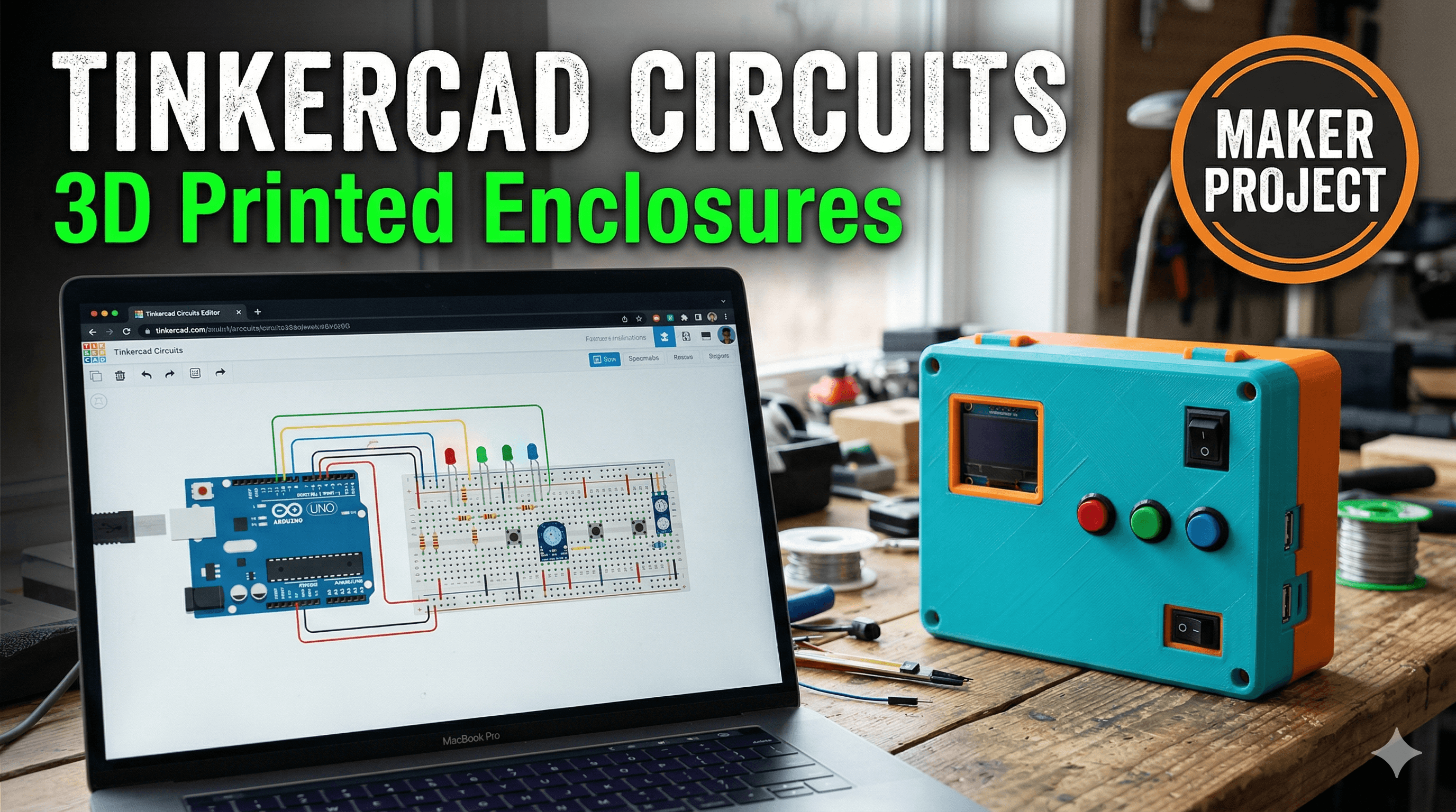
Alright, let's get down to business. Imagine you're making a simple, battery-powered night light with a light-dependent resistor (LDR) and a few LEDs. Pretty standard stuff, right? First things first, you'd head over to the Tinkercad Circuits editor. You drag out an Arduino Uno (or a bare ATtiny85 if you're going for super compact!), some LEDs, resistors, an LDR, and a breadboard. Wire it all up virtually. Write a simple sketch to turn the LEDs on when it's dark and off when it's bright.
Now, this is where the simulation magic happens. Hit that "Start Simulation" button. Does it work? Does the LED brighten and dim as you virtually "change" the light intensity on the LDR? If not, troubleshoot it right there. It costs you nothing but time, and you're not burning out actual components. Believe me, I've had my share of smoking ICs back in the day before I embraced simulation tools. It's way cheaper to virtually fry a chip than to buy a new one, especially when you're running a small business and every rupee counts.
Once your circuit is working perfectly in the simulation, you've got a solid foundation. And if you're wondering about getting physical components for your next project, you can often find great deals. For example, a basic Arduino Uno starter kit on Amazon India might set you back around ₹1500-₹2000, which is fantastic value for everything you get to start experimenting.
Step 2: Transitioning to the Physical World & Designing Your Enclosure
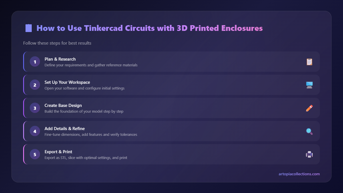
Now that your circuit is singing, it's time to think about the physical components. You'll need to gather your actual Arduino board (or whatever microcontroller you're using), your LEDs, resistors, LDR, and a battery holder. Look, it's always a good idea to lay out your physical components roughly on a table. See how much space they take up. This gives you a preliminary mental model for your enclosure design.
Here's the cool part: many of the components in Tinkercad Circuits actually have corresponding 3D models or at least accurate dimensions. For instance, if you used an Arduino Uno, you can switch over to the 3D design part of Tinkercad and import a pre-made Arduino Uno model or simply create a box with its exact dimensions. This is crucial for precise enclosure design. If you can't find an exact model, measure your physical component with a caliper. Even a cheap digital caliper from Amazon.in for ₹500-₹800 is an absolute must-have tool for any maker. Trust me, it pays for itself a hundred times over.
When you're designing your enclosure, think about a few key things:
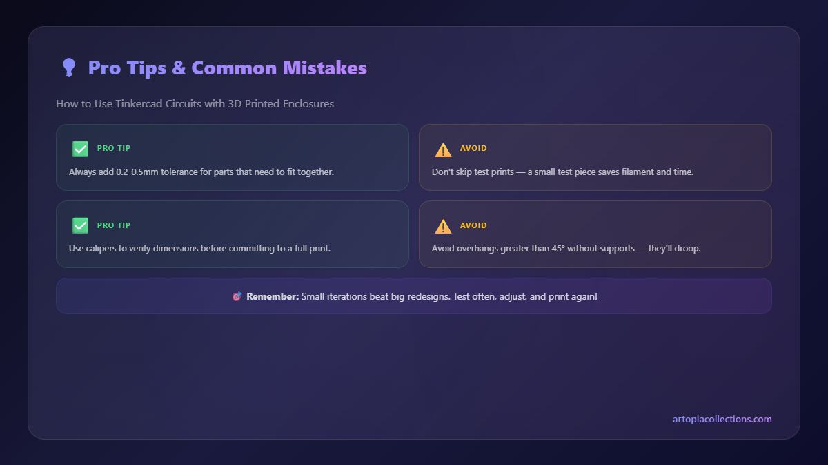
- Mounting Holes: How will your board sit inside? Most microcontrollers have standard mounting holes. Use cylindrical "hole" shapes in Tinkercad to create these, making them slightly larger (e.g., 3.2mm for M3 screws) to account for print tolerances.
- Cutouts: Need a USB port accessible? A power jack? A slot for your LDR to peek out? Use "hole" shapes for these. Again, add a small tolerance (0.2-0.5mm) so things aren't too tight.
- Lid Mechanism: Will it be a snap-fit? Screwed down? My personal preference for most projects is a simple screw-on lid using M3 screws. It's secure, and you can easily reopen it for modifications. Create posts inside the enclosure with holes for self-tapping screws or heat-set inserts.
- LEDs & Buttons: If you have external LEDs or pushbuttons, ensure their holes are precise. For LEDs, a 5mm hole for a 5mm LED usually works, but sometimes 5.1mm or 5.2mm is better, depending on your printer's accuracy.
- Ventilation: For circuits that might generate heat (like motor drivers or powerful microcontrollers), consider adding some vent slots or a grill design. This isn't critical for our simple night light, but it's good practice.
Don't forget to add a bit of wall thickness – generally 1.5mm to 2mm is good for PLA or PETG to give it structural integrity without wasting too much filament. And hey, why not put your business logo on it? A subtle debossed or embossed logo makes it look super professional. We do it for all our custom projects here at ArtOPIA, and clients absolutely love that personalized touch!
Step 3: Printing Your Custom Enclosure
Once your enclosure design is finalized in Tinkercad (or whatever CAD software you end up using for more complex stuff), it's time to slice and print! Now, what filament should you use? For most indoor, aesthetic projects, PLA filament is your best friend. It’s easy to print, relatively inexpensive (you can get a good kilo spool for ₹800-₹1500 from brands like eSun, Prusament, or even some local Indian suppliers), and comes in a zillion colours. If your project needs more durability, heat resistance, or will be exposed to the elements, then PETG is a better choice, though it can be a bit trickier to print.
For printing, I mostly rely on my trusty Creality Ender 3 V2 for quick prototypes and some custom orders, and sometimes a Prusa Mini+ for higher quality, finer detail pieces. Both are excellent machines. For your enclosure, I'd recommend:
- Layer Height: 0.2mm is usually a good balance of speed and quality.
- Infill: 15-20% rectilinear or grid infill is typically sufficient. No need to go higher unless it's a structural component.
- Supports: You'll likely need supports for screw holes or any overhangs for the lid. Set them to "tree supports" in Cura or PrusaSlicer for easier removal.
- Brim/Raft: If you're worried about adhesion, especially for taller prints, a brim can help keep it stuck to the build plate.
The beauty of 3D printing is that if the first print isn't perfect, you can tweak your design in Tinkercad and print again. Maybe a hole is too small, or the lid is too tight. A few iterations are totally normal. It’s part of the process, a joyful, iterative dance between virtual and physical. I've had projects that took three or four enclosure revisions before I was truly happy, and that's perfectly okay. It's how you learn, right?
Step 4: Assembly – Bringing It All Together
Once your enclosure parts are printed, carefully remove any supports. A good deburring tool or even a craft knife can help clean up the edges. Now, it's time to populate your enclosure. This is where your soldering skills come in handy. Solder your components to a perfboard or a custom PCB, ensuring they fit the space you designed for them. Sometimes, I'll even skip the breadboard entirely and solder directly to a small perfboard right after simulating in Tinkercad, especially for compact designs.
Carefully insert your microcontroller, connect your wires to the external components (LEDs, LDR), and route them neatly. Use small M3 screws (easily available at any hardware shop for ₹1-₹2 each) to secure your PCB to the mounting posts. If you've planned for it, heat-set inserts can give an even more professional, durable finish, but for hobby projects and many custom orders, self-tapping screws directly into plastic posts work just fine.
Close up the lid, screw it down, and give your finished product a final once-over. Doesn't that look infinitely better than a tangled mess of wires on a breadboard? It's protected, it's tidy, and it looks like a legitimate product. Honestly, the satisfaction of holding a finished piece, knowing you designed every part of it, both the electronics and the physical housing, is just immense.
Why This Workflow Matters for Makers & Small Businesses
This approach of using Tinkercad Circuits with 3D printed enclosures isn't just a neat trick; it's a fundamental workflow that can transform how you approach your electronic projects, whether you're a hobbyist or running a small business like ArtOPIA.
- Professionalism: A custom-fit enclosure elevates your project from a "DIY hack" to a "finished product." This is HUGE for client perception.
- Protection: Your sensitive electronics are safe from dust, accidental spills, and general wear and tear.
- Customization: You're not limited to off-the-shelf project boxes. You can make an enclosure that perfectly fits your unique components and aesthetic vision. Need a specific button layout? No problem. A funky shape? Go for it!
- Cost-Effective: For one-offs or small batches, 3D printing custom enclosures is far more economical than injection molding or even buying multiple standard enclosures that don't quite fit. A small enclosure might only use ₹20-₹50 worth of filament.
- Rapid Prototyping: The speed at which you can go from circuit idea to physical, housed prototype is incredible. This allows for quick testing and iteration, essential for product development.
So, there you have it. The secret sauce, at least a big part of it, to making your electronic creations truly shine. Tinkercad Circuits provides an accessible playground for your electronic designs, and 3D printing offers the ultimate flexibility for bringing those designs into the physical world with custom, professional-looking enclosures. It’s a powerful combination that, in my experience, genuinely empowers creators to do more and do it better.
Now, go forth, experiment, design, and print! And if you ever need some inspiration or even a custom print job, don't hesitate to check out our collection of unique 3D printed items and custom services over at ArtOPIA Collections. We’re always excited to see what amazing things people are creating.